
Why green Hydrogen is paramount?
To achieve carbon neutrality, promote sustainable development, and mitigate environmental pollution, there is a global shift towards renewable energy sources such as solar, wind, geothermal, and hydrogen to replace fossil fuels. To address the intermittency of renewable energy, the development of efficient and reliable energy storage systems is crucial. Among various energy storage technologies, rechargeable batteries, fuel cells, supercapacitors, and electrolysis for hydrogen production are recognized as viable options. Governments worldwide recognize the significance of hydrogen as a sustainable energy solution and are actively implementing policies and initiatives to advance hydrogen technology. In order to reach the specified goals, a clear transition from carbon-based energy sources towards renewable and carbon-free energy carriers is indispensable. Electricity and hydrogen – as far as provided from wind, solar or hydro power – are carbon-free secondary energy carriers for storing, transporting and using energy. The introduction of a renewable hydrogen economy, like shown in Fig. 1 [1,2].
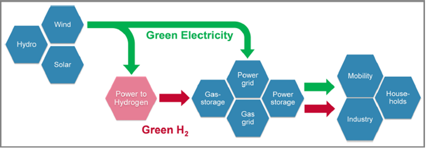
Vision of a renewable hydrogen economy. [2]
The EU’s Hydrogen Strategy puts green hydrogen in the spotlight as a priority to reach carbon neutrality by 2050 and for the global effort to implement the Paris Agreement while working towards zero pollution. Hydrogen and electrolysers have accordingly become a focus of technology development.
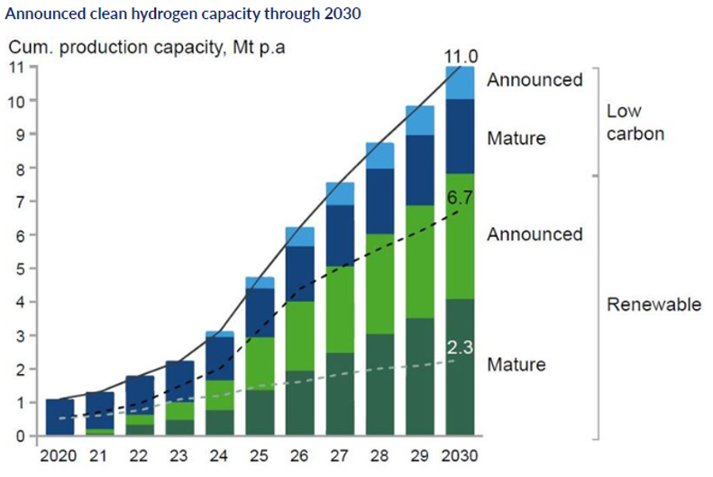
Announced clean hydrogen capacity through 2030 [3]
The cost of producing green hydrogen – between $2.5 and $6 per kg at present – must reduce substantially for it to become a serious contender, yet given adequate investment and sufficient supply of materials this should be achievable in the long term. The cost of generating the renewable electricity on which green hydrogen relies has declined over time to the point where the levelised cost of electricity from solar and wind is already below the cost of electricity derived from coal and natural gas, like shown in Fig. 2. Current world electrolyser capacity is about 3 GW; scaling this up to 70 GW by 2030[3].
Water electrolysis technologies
There are four types of water electrolyser for producing green hydrogen. Alkaline (ALK) and proton exchange membrane (PEM) electrolysers are already in commercial use at scale. Anion exchange membrane (AEM) and solid oxide (SOE) electrolysers are still under development, like shown in Fig. 3. A PEM electrolyser consists of the anode and cathode catalysts (mainly Ir and Pt, respectively) and an acidic membrane in the form of a solid electrolyte.The advantageous feature of PEM electrolysis is the possibility of using high pressure on the cathode side while the anode can be operated at atmospheric pressure.The purity of the produced gases in the PEM electrolyzer is higher than that of alkaline electrolysis due to the low gas crossover rate of the polymer electrolyte, and the PEM electrolyzer can operate at a current density of 2 A cm−2.Therefore, the PEM electrolysis can achieve high efficiency with a fast response compared to the alkaline electrolysis, see Table 1.Overall, PEM electrolysis has many advantages and is considered a promising water electrolysis technology.[4]
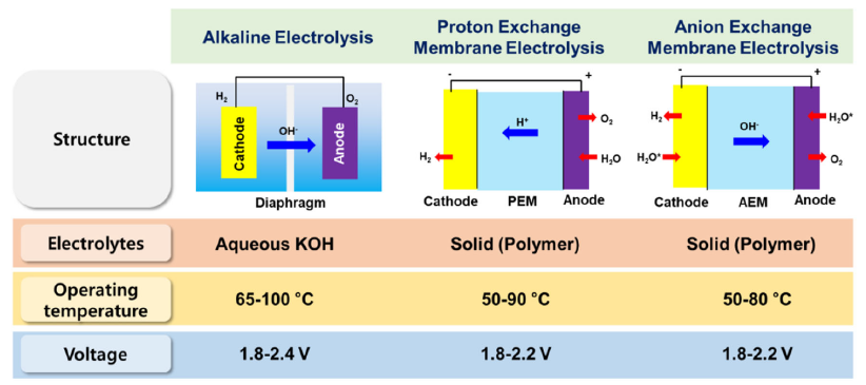
Figure 3. Comparison of water electrolysis technologies. [4]
Table 1. Comparison of characteristics of alkaline and PEM electrolyser [5]
| PEM | ALK | |
| Cold start (to nominal load)/minutes | < 20 | < 50 |
| Lifetime (stack)/hours | 50,000-100,000 | 60,000 |
| Stack unit size/MW | 1 | 1 |
| Current density(A/m2) | 2000-4000 | 10000-20000 |
| Hydrogen purity(%) | 99.99 | 99.95 |
| Hydrogen production rate/m3h-1 | 400 | 1,000 |
Electrolyser cost breakdown
Deep links exist between hydrogen and platinum-group metals (PGMs) in the fields of energy, industry and transport, and demand for PGMs in these applications will expand progressively over the next decades, with the strongest growth coming from the greening of hydrogen production using electrolysers.At the core of the PEM electrolyser, the catalyst-coated membrane (CCM) containing the PGMs represents about 10% of the entire system cost, shown in Fig. 4. Reducing this cost element will involve reduction of PGM loadings, particularly iridium which is a by-product of platinum refining and which therefore has limited availability.Iridium and platinum would be hard to substitute entirely as they are technically the best fit for PEM electrolysers. Innovation to reduce the intensity of PGM use is based on some familiar themes in catalyst surface chemistry and engineering – for example, by increasing the catalyst surface area and using thinner layers of catalyst coating material. PGM fabricators have had high success rates using these methods over many years in reducing PGM loadings.
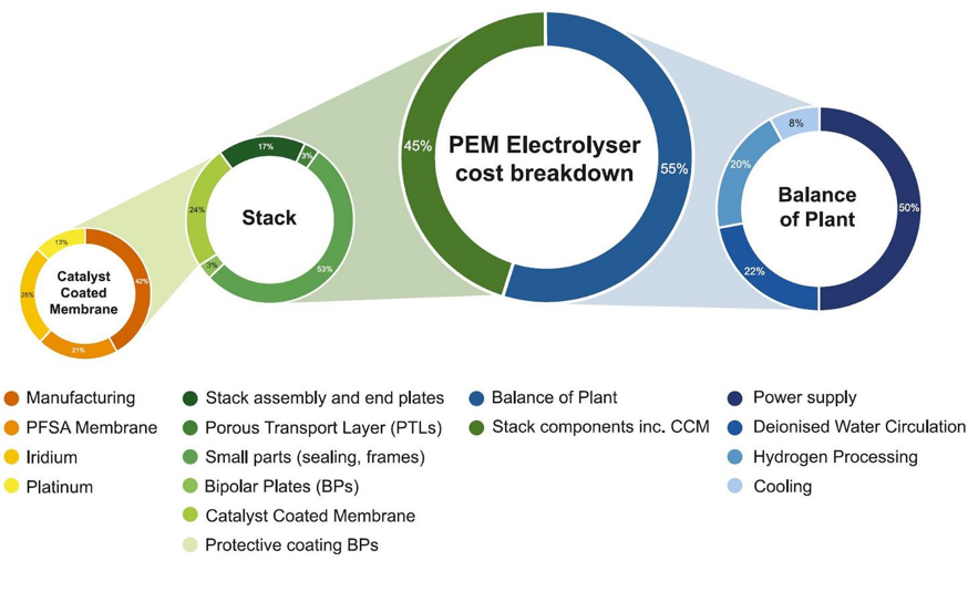
Figure 4. PEM electrolyser cost breakdown.[2]
In PEM electrolyser, the core components mainly include bipolar plates (BPs), gas diffusion layer (GDL), PEM, and electrocatalysts of cathode and anode. Fig.5 shows the schematic diagram of a single cell in a PEM stack. The two half-cells are separated by the PEM, which transports protons during the reaction and blocks the passage of the product gas. The catalysts are directly applied to the membrane or porous transport layers. In most cell designs, the catalyst layers deposited on the membrane, forming the key component of the cells, that is, the membrane electrode assembly (MEA). Two porous transport layers (also known as GDL) are sandwiched on both sides of the MEA. The flow-field plates (also known as BPs) encapsulate the two half-cells, acting as a transfer of charge, mass, heat, and establish contact to the external power supply. Hydrogen and oxygen products pass through the catalyst surface, GDL, and BPs in succession to release out of the cells. Expressly, the half-cells also need to be supplemented with some sealing elements to prevent gas and water leakage[6].
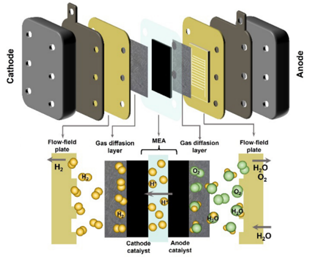
Figure 5. Stack structure and key materials of PEM electrolyser.[6]
Membrane electrode assembly functions
The PEM stack capital cost is dominated by the cost of the membrane electrode assembly (shown in Figure 6), which consists of a perfluorsulfonic membrane, anode and cathode catalyst, and diffusion layers. The anode side of the cell where the titanium porous transport layer (PTL) and iridium-based catalysts dominate the technoeconomics. In recent research showing that (i) oxygen transport through the titanium PTL may be a crucial limiting factor contributing to performance decline, (ii) high performance at ultra-low loadings without MPLs is possible, (iii) catalyst layer ionic resistance dominates over electronic resistance when ionomer volume fraction is higher than 20% [7].
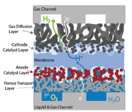
Figure 6. Detail of water and oxygen flow within the anode catalyst and porous transport layers.[7]
The result also indicates that PTL structural differences could lead to a dramatic variance in oxygen distribution within the catalyst layer/PTL (CL/PTL), mid-PTL, and PTL/channel. The broader and more even oxygen distribution indicates more oxygen transport pathways and less oxygen removal resistance, likely eases water permeation to active sites, which should result in a lower overall mass transport overpotential during PEM electrolysers operation. Shown in Figure 7, the impact of the PTL structure on the oxygen distribution is clearly evident. A highly porous and low tortuosity PTL achieves the highest oxygen transport pathway across each interface of CL/PTL, mid-PTL, and PTL/channel as well as through plane. A high tortuosity and low porosity PTL channels O2 through narrow bands of preferential pathways, limiting the diffusion of oxygen across the interfaces and through the plane of the PTL. Which strikingly results in no oxygen at the channel/PTL interface, under the land of the channel [7].
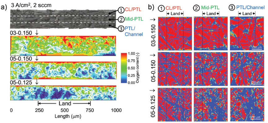
Figure 7. Summary plots detailing the oxygen distribution at interface of CL/PTL, middle interface of PTL, and interface of PTL/flow field channel for the samples of 03-0.150, 05-0.150, and 05-0.125, respectively. [7]
Electrocatalysts of PEM electrolyser
The efficiency of hydrogen evolution reaction (HER) in PEM electrolysers is mainly determined by the catalytic activity and stability of the catalysts, such as commonly used commercial platinum/carbon (Pt/C) composite materials. The performance of the catalysts depends on the dispersibility of the active materials and their ability to maintain stability during the HER process, avoiding aggregation that could lead to a decrease or even loss of catalytic functionality. Several studies have shown that synthesizing the active materials with chemical functional groups and stably dispersing them within the carbon structure can not only reduce the loading of active materials but also enhance the efficiency of HER. This contributes to a significant reduction in the cost of hydrogen production in PEM electrolysis. The structure of the cathodic active materials and a simplified reaction mechanism are shown in Figure 8 [8].
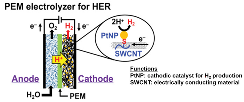
Figure 8. PEM electrolyser for HER.[8]
The development of large-scale electrolysis technology is experiencing rapid growth. This technology offers more economic potential compared to fossil fuel-based hydrogen energy, primarily due to the availability of low-cost renewable power sources and advancements in materials and manufacturing, which have demonstrated the feasibility of the technology. However, clear strategies and investments are needed in the coming years to achieve significant cost and performance improvements in low-temperature electrolysis. While new advanced water splitting technologies may eventually replace existing options, ALK and PEM will be the main foundational technologies for electrolytic hydrogen production in the next decade. Even in the most optimistic scenarios, solid AEM technology will require several years to achieve significant deployment and market penetration at the MW scale, while other technologies will take even longer due to the need for equipment and system design, as well as the integration of new materials. Therefore, research and development efforts should include the integration of advanced components into existing commercial technologies while exploring new ideas and technological approaches. By developing electrolysis systems, renewable hydrogen energy has the potential to impact various industries in the energy sector, from industrial ammonia synthesis to the production of renewable fuels, among others [9].
Reference
- 邁向2050年淨零碳排的新救星—氫能Available from: https://www.materialsnet.com.tw/DocView.aspx?id=48815
- Alexander, T., et al., Renewable Hydrogen: Modular Concepts from Production over Storage to the Consumer. Chemie Ingenieur Technik, 2021. 93(4): p. 1-12.
- The greening of hydrogen Available from: https://www.sfa-oxford.com/market-news-and-insights/sfa-the-greening-of-hydrogen/
- Lee, S., A, et al., Anion exchange membrane water electrolysis for sustainable large‐scale hydrogen production. Carbon Neutralization, 2022. 22: p26-48.
- Guo, Y., et al., Comparison between hydrogen production by alkaline water electrolysis and hydrogen production by PEM electrolysis. IOP Conference Series: Earth and Environmental Science, 2019. (371) 042022.
- Chen, H., Zou, X., et al., Status and perspectives of key materials for PEM electrolyzer. Nano Research Energy, 2022. (1): e9120032.
- Zenyuk, I., V., et al., Insights into Interfacial and Bulk Transport Phenomena Affecting Proton Exchange Membrane Water Electrolyzer Performance at Ultra-Low Iridium Loadings. Advanced Science, 2021. (8) 2102950.
- Ito, Y., Kawamoto, M., et al., Highly Efficient Electrocatalytic Hydrogen Production over Carbon Nanotubes Loaded with Platinum Nanoparticles Using Solution Processing. Advanced Materials Interfaces, 2023. (10) 2300094.
- Ayers, K., et al., Perspectives on Low-Temperature Electrolysis and Potential for Renewable Hydrogen at Scale. Journal Annual review of chemical and biomolecular engineering, 2019. 10(1) p. 219-239.